1: INTRODUCTION: Provide the complete necessary conceptual background concepts with clear explanation and the introduction required to understand and answer the given question. Add an Explanation block at the end of the introduction by adding various relevant supporting statements and explaining the introduction concisely. Note: Do not use personal pronouns like I, we, you, etc. The response must look as if it is written by a human. Explanation: Articulate the importance of the introduction, providing more relevant comprehensive supporting statements that link these concepts directly to the question. This explanation should clarify how the introduction aids in comprehending the subsequent steps. 2: Presentation of Relevant Formulas Required To Solve & Representing The Given Data For The Given Data: List and also describe all formulas required to solve the question. Ensure each formula is presented clearly and is directly applicable to the problem. Explanation: Detail the derivation or rationale behind each formula, explaining its relevance and necessity in the context of the problem-solving process. Use more relavent comprehensive supporting statements to reinforce the significance of these mathematical tools. 3: A Detailed Step-by-Step Solution: Please provide a structured step-by-step solution to the given question, by incorporating any relevant data provided. This should include all necessary mathematical calculations presented in a logical and clear manner. The solution must be comprehensive, addressing all aspects of the question without omission. Explanation: For each step in the solution, provide a thorough explanation of the calculations performed, including how each step contributes to solving the overall problem. Add more relevant comprehensive Supporting statements should enhance understanding and connect each calculation back to the core question. Conclusion: Conclude with a concise summary of the solution, succinctly presenting the final answer derived from the calculations.A solid shaft rotates and carries the minor shock loading, as shown in the Figure. The torque fluctuates 5% each way from the mean value, and the shaft is to be machined from unnotched steel. (a) Draw load, shear force, and bending moment diagrams for the shaft in the xy and xz planes. Also, draw diagrams showing the intensity of torque along the length of the shaft. (b) At different points of the shaft, A, B, C, and D, calculate the equivalent stresses in preparation for proper diameter determination. (c) For a reliability of 99%, determine the diameter of the shaft at all points, including C, D. The safety factor is considered as per the designer's comment, but it shall be greater than 1. (d) Design the relevant key for the keyway at C and D. (Note: Each group shall choose a different material and other designing parameters, like safety factor compared to others) J 04m T 0.6 m T 0.4m | 1 2kN TNT = 1 ake. / a / te Jo dl O/ > ed 4 1 B,=6.43 a” A,=257 r=02m v 8 i ) SKN Y 3 6 kN
Question:
1: INTRODUCTION:
Provide the complete necessary conceptual background concepts with clear explanation and the introduction required to understand and answer the given question. Add an Explanation block at the end of the introduction by adding various relevant supporting statements and explaining the introduction concisely.
Note: Do not use personal pronouns like I, we, you, etc. The response must look as if it is written by a human.
Explanation: Articulate the importance of the introduction, providing more relevant comprehensive supporting statements that link these concepts directly to the question. This explanation should clarify how the introduction aids in comprehending the subsequent steps.
2: Presentation of Relevant Formulas Required To Solve & Representing The Given Data For The Given Data:
List and also describe all formulas required to solve the question. Ensure each formula is presented clearly and is directly applicable to the problem.
Explanation: Detail the derivation or rationale behind each formula, explaining its relevance and necessity in the context of the problem-solving process. Use more relavent comprehensive supporting statements to reinforce the significance of these mathematical tools.
3: A Detailed Step-by-Step Solution:
Please provide a structured step-by-step solution to the given question, by incorporating any relevant data provided. This should include all necessary mathematical calculations presented in a logical and clear manner. The solution must be comprehensive, addressing all aspects of the question without omission.
Explanation: For each step in the solution, provide a thorough explanation of the calculations performed, including how each step contributes to solving the overall problem. Add more relevant comprehensive Supporting statements should enhance understanding and connect each calculation back to the core question.
Conclusion:
Conclude with a concise summary of the solution, succinctly presenting the final answer derived from the calculations.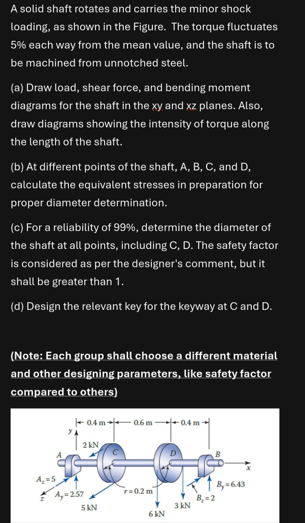 A solid shaft rotates and carries the minor shock
loading, as shown in the Figure. The torque fluctuates
5% each way from the mean value, and the shaft is to
be machined from unnotched steel.
(a) Draw load, shear force, and bending moment
diagrams for the shaft in the xy and xz planes. Also,
draw diagrams showing the intensity of torque along
the length of the shaft.
(b) At different points of the shaft, A, B, C, and D,
calculate the equivalent stresses in preparation for
proper diameter determination.
(c) For a reliability of 99%, determine the diameter of
the shaft at all points, including C, D. The safety factor
is considered as per the designer's comment, but it
shall be greater than 1.
(d) Design the relevant key for the keyway at C and D.
(Note: Each group shall choose a different material
and other designing parameters, like safety factor
compared to others)
J 04m T 0.6 m T 0.4m |
1
2kN
TNT
= 1 ake. / a /
te Jo dl O/ > ed 4 1 B,=6.43
a” A,=257 r=02m v 8 i
) SKN Y 3
6 kN
A solid shaft rotates and carries the minor shock
loading, as shown in the Figure. The torque fluctuates
5% each way from the mean value, and the shaft is to
be machined from unnotched steel.
(a) Draw load, shear force, and bending moment
diagrams for the shaft in the xy and xz planes. Also,
draw diagrams showing the intensity of torque along
the length of the shaft.
(b) At different points of the shaft, A, B, C, and D,
calculate the equivalent stresses in preparation for
proper diameter determination.
(c) For a reliability of 99%, determine the diameter of
the shaft at all points, including C, D. The safety factor
is considered as per the designer's comment, but it
shall be greater than 1.
(d) Design the relevant key for the keyway at C and D.
(Note: Each group shall choose a different material
and other designing parameters, like safety factor
compared to others)
J 04m T 0.6 m T 0.4m |
1
2kN
TNT
= 1 ake. / a /
te Jo dl O/ > ed 4 1 B,=6.43
a” A,=257 r=02m v 8 i
) SKN Y 3
6 kN
Asked by: shaik baji
Created at: 2025-10-09 09:09:33
Final Answer:
📢 Instructions:
- Ask anything relatd to above question only.
- For new Question goto :