Act like a helpful tutor and exlain me step-by-step solution with explanation and final answer:1. The design of a shell and tube heat exchanger necessitates a rigorous evaluation of the overall heat transfer coefficient, which is a composite parameter accounting for all thermal resistances in the system. The diagram below illustrates the cross-section of a single tube, showing the inner fluid film, the inner fouling layer, cuter fouling layer are tube wall, and outer fluid film, with their respective thermal resistances and the temperature profile across them. «For a counter-flow shell and tube heat exchanger operating under steady-state conditions, with constant fluid properties and a uniform overall heat transfer coefficient U, derive the expression for U based on the summation of the individual thermal resistances offered by the inner and outer fluid film, the tube wall material, and the fouling layers on both the tube-side and shell-side surfaces, considering the ozter side wall film material and the fouling lay, on both the tube-side and shell-side surfaces, considering the respective heat transfer areas. i. Analyse the impact of increased fouling on either the shell-side or tube-side on the value of the overall heat transfer coefficient and the subsequent effect on the required heat transfer surface area to maintain a specified heat duty. ii. Deduce the relationship for the Logarithmic Mean Temperature Difference (LMTD) for a pure counter-flow heat exchanger by performing a heat balance over a differential element of the exchanger length, assuming a constant U and constant specific heats for both fluids. + When dealing with multi-pass heat exchangers, the deviation from true counter-flow behaveur requires a correction to the LMTD. i. Obtain the expression for the LMTD correction factor (F), defined as the ratio of the actual mean temperature difference in the multi-pass exchanger to the LMTD of a counter-flow exchanger operating between the same inlet and outlet temperatures, by considering the temperature effectiveness (P) and the heat capacity rate ratio (R). ii. Reduce the expression for the heat transfer rate Q to the form Q = U * A * F « LMTD counterfiow, where A is the total heat transfer area, and discuss how the value of F is determined from design charts based on P and R for a specific exchanger configuration (e.g., 1-shell pass, 2-tube passes). Ro 4 Rei = a 2 ha; \\ ; Ns Y, Rome i07 " EX "hts Ne Re Q 2. A solid steel sphere with a diameter of 5 cm, initially at a uniform temperature of 450 °C, is suddenly immersed in a large oil bath maintained at a constant temperature of 50 °C. The convection heat transfer coefficient between the sphere surface and the oil is 120 W/(m2-K). The properties of the steel are: density p = 7800 kg/m? specific heat capacity C, = 480 J/(kg'K), and thermal conductivity k= 50 W/mK). +. Calculate the Biot number (Bi) for this system to justify the validity of the lumped capacitance method, and subsequently determine the time required for the center of the sphere to cool down to a temperature of 150 °C. «=. Based on the governing differential equation for the lumped capacitance method, reduce the expression for the temperature-time history, T(t), to a dimensionless form, Fae = exp(~Bi Fo), where Fo is the Fourier number, by appropriately defining the dimensionless time and position variables.
Question:
Act like a helpful tutor and exlain me step-by-step solution with explanation and final answer: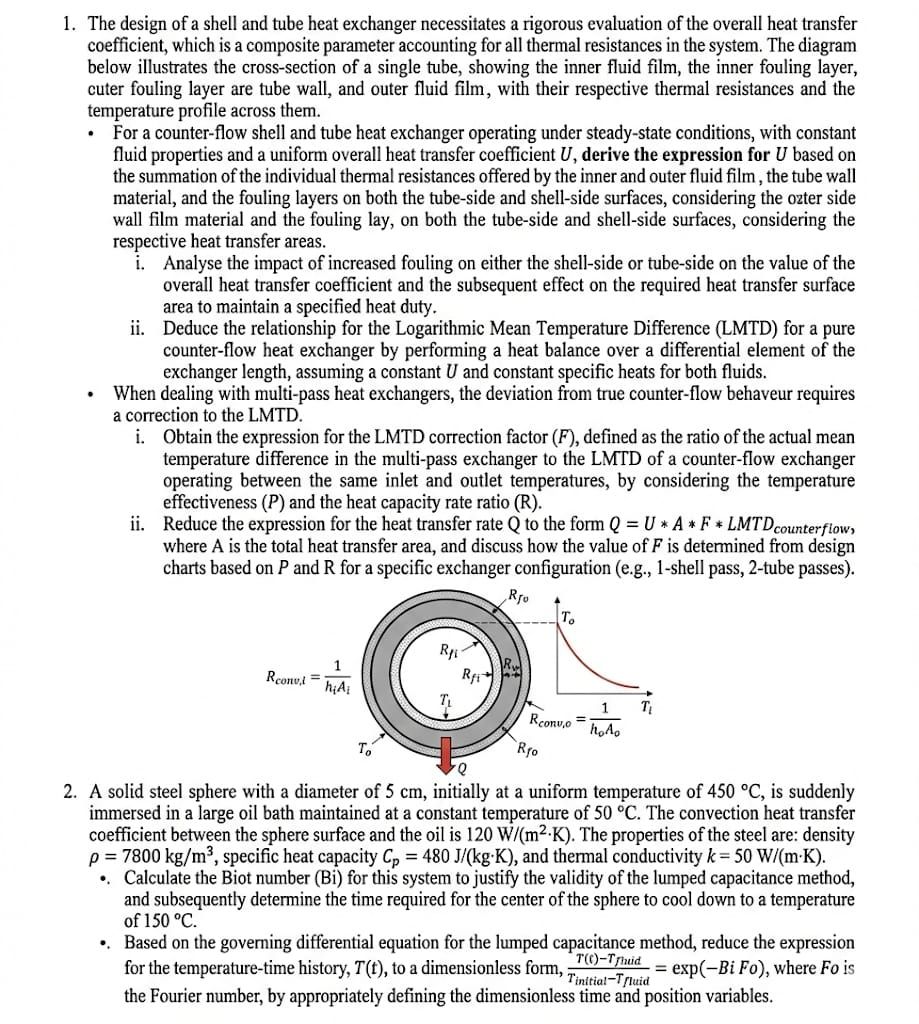 1. The design of a shell and tube heat exchanger necessitates a rigorous evaluation of the overall heat transfer
coefficient, which is a composite parameter accounting for all thermal resistances in the system. The diagram
below illustrates the cross-section of a single tube, showing the inner fluid film, the inner fouling layer,
cuter fouling layer are tube wall, and outer fluid film, with their respective thermal resistances and the
temperature profile across them.
«For a counter-flow shell and tube heat exchanger operating under steady-state conditions, with constant
fluid properties and a uniform overall heat transfer coefficient U, derive the expression for U based on
the summation of the individual thermal resistances offered by the inner and outer fluid film, the tube wall
material, and the fouling layers on both the tube-side and shell-side surfaces, considering the ozter side
wall film material and the fouling lay, on both the tube-side and shell-side surfaces, considering the
respective heat transfer areas.
i. Analyse the impact of increased fouling on either the shell-side or tube-side on the value of the
overall heat transfer coefficient and the subsequent effect on the required heat transfer surface
area to maintain a specified heat duty.
ii. Deduce the relationship for the Logarithmic Mean Temperature Difference (LMTD) for a pure
counter-flow heat exchanger by performing a heat balance over a differential element of the
exchanger length, assuming a constant U and constant specific heats for both fluids.
+ When dealing with multi-pass heat exchangers, the deviation from true counter-flow behaveur requires
a correction to the LMTD.
i. Obtain the expression for the LMTD correction factor (F), defined as the ratio of the actual mean
temperature difference in the multi-pass exchanger to the LMTD of a counter-flow exchanger
operating between the same inlet and outlet temperatures, by considering the temperature
effectiveness (P) and the heat capacity rate ratio (R).
ii. Reduce the expression for the heat transfer rate Q to the form Q = U * A * F « LMTD counterfiow,
where A is the total heat transfer area, and discuss how the value of F is determined from design
charts based on P and R for a specific exchanger configuration (e.g., 1-shell pass, 2-tube passes).
Ro 4
Rei = a 2
ha; \\ ;
Ns Y, Rome i07 "
EX "hts
Ne Re
Q
2. A solid steel sphere with a diameter of 5 cm, initially at a uniform temperature of 450 °C, is suddenly
immersed in a large oil bath maintained at a constant temperature of 50 °C. The convection heat transfer
coefficient between the sphere surface and the oil is 120 W/(m2-K). The properties of the steel are: density
p = 7800 kg/m? specific heat capacity C, = 480 J/(kg'K), and thermal conductivity k= 50 W/mK).
+. Calculate the Biot number (Bi) for this system to justify the validity of the lumped capacitance method,
and subsequently determine the time required for the center of the sphere to cool down to a temperature
of 150 °C.
«=. Based on the governing differential equation for the lumped capacitance method, reduce the expression
for the temperature-time history, T(t), to a dimensionless form, Fae = exp(~Bi Fo), where Fo is
the Fourier number, by appropriately defining the dimensionless time and position variables.
1. The design of a shell and tube heat exchanger necessitates a rigorous evaluation of the overall heat transfer
coefficient, which is a composite parameter accounting for all thermal resistances in the system. The diagram
below illustrates the cross-section of a single tube, showing the inner fluid film, the inner fouling layer,
cuter fouling layer are tube wall, and outer fluid film, with their respective thermal resistances and the
temperature profile across them.
«For a counter-flow shell and tube heat exchanger operating under steady-state conditions, with constant
fluid properties and a uniform overall heat transfer coefficient U, derive the expression for U based on
the summation of the individual thermal resistances offered by the inner and outer fluid film, the tube wall
material, and the fouling layers on both the tube-side and shell-side surfaces, considering the ozter side
wall film material and the fouling lay, on both the tube-side and shell-side surfaces, considering the
respective heat transfer areas.
i. Analyse the impact of increased fouling on either the shell-side or tube-side on the value of the
overall heat transfer coefficient and the subsequent effect on the required heat transfer surface
area to maintain a specified heat duty.
ii. Deduce the relationship for the Logarithmic Mean Temperature Difference (LMTD) for a pure
counter-flow heat exchanger by performing a heat balance over a differential element of the
exchanger length, assuming a constant U and constant specific heats for both fluids.
+ When dealing with multi-pass heat exchangers, the deviation from true counter-flow behaveur requires
a correction to the LMTD.
i. Obtain the expression for the LMTD correction factor (F), defined as the ratio of the actual mean
temperature difference in the multi-pass exchanger to the LMTD of a counter-flow exchanger
operating between the same inlet and outlet temperatures, by considering the temperature
effectiveness (P) and the heat capacity rate ratio (R).
ii. Reduce the expression for the heat transfer rate Q to the form Q = U * A * F « LMTD counterfiow,
where A is the total heat transfer area, and discuss how the value of F is determined from design
charts based on P and R for a specific exchanger configuration (e.g., 1-shell pass, 2-tube passes).
Ro 4
Rei = a 2
ha; \\ ;
Ns Y, Rome i07 "
EX "hts
Ne Re
Q
2. A solid steel sphere with a diameter of 5 cm, initially at a uniform temperature of 450 °C, is suddenly
immersed in a large oil bath maintained at a constant temperature of 50 °C. The convection heat transfer
coefficient between the sphere surface and the oil is 120 W/(m2-K). The properties of the steel are: density
p = 7800 kg/m? specific heat capacity C, = 480 J/(kg'K), and thermal conductivity k= 50 W/mK).
+. Calculate the Biot number (Bi) for this system to justify the validity of the lumped capacitance method,
and subsequently determine the time required for the center of the sphere to cool down to a temperature
of 150 °C.
«=. Based on the governing differential equation for the lumped capacitance method, reduce the expression
for the temperature-time history, T(t), to a dimensionless form, Fae = exp(~Bi Fo), where Fo is
the Fourier number, by appropriately defining the dimensionless time and position variables.
Asked by: Francis
Created at: 2026-02-09 07:01:28
Final Answer:
📢 Instructions:
- Ask anything relatd to above question only.
- For new Question goto :