Give step-by-step solution with explanation and final answer:_ a 1% . 0, Question #2 p Zz "2 7 Fe, SY (OO | THR d, Xx As d AR x dle, ply 2 0 Figure 2 4 Find the forward kinematics of the cylindrical arm in Figure 2
Question:
Give step-by-step solution with explanation and final answer: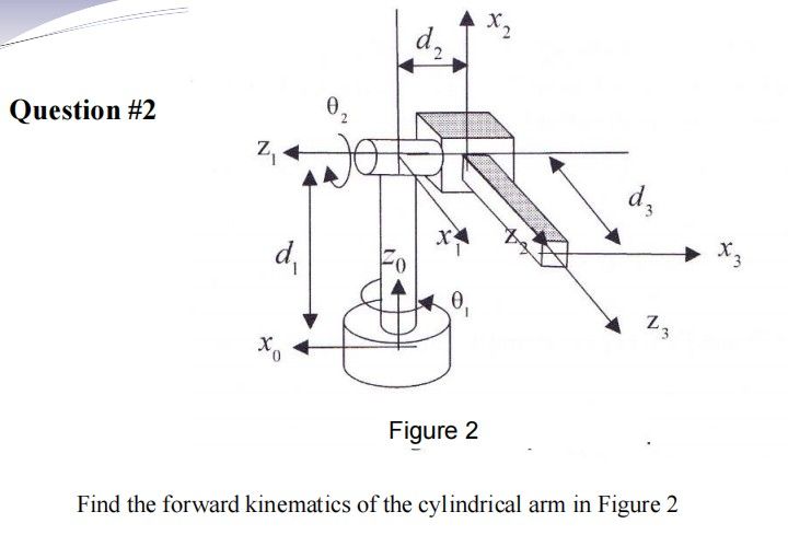 _ a 1%
. 0,
Question #2 p
Zz "2 7 Fe, SY (OO
| THR
d,
Xx As
d AR x
dle,
ply 2
0
Figure 2 4
Find the forward kinematics of the cylindrical arm in Figure 2
_ a 1%
. 0,
Question #2 p
Zz "2 7 Fe, SY (OO
| THR
d,
Xx As
d AR x
dle,
ply 2
0
Figure 2 4
Find the forward kinematics of the cylindrical arm in Figure 2
This is AI generated Response.
Asked by: Rahul
Created at: 2026-01-23 20:27:18
Asked by: Rahul
Created at: 2026-01-23 20:27:18
Final Answer:
Rendered
Raw Text
Did you like this answer?
# Forward Kinematics of Cylindrical Arm (Figure 2)
Let's solve the forward kinematics for the cylindrical robot arm shown.
## **Step 1: Assign D-H Parameters**
The cylindrical arm has:
- 1 revolute joint (\(\theta_1\))
- 2 prismatic joints (\(d_2, d_3\))
Let’s define the D-H parameters for each joint.
| Link | \(\theta_i\) | \(d_i\) | \(a_i\) | \(\alpha_i\) |
|------|:-----------:|:-------:|:-------:|:------------:|
| 1 | \(\theta_1\)| \(d_1\) | | \(^\circ\) |
| 2 | \(\) | \(d_2\) | | \(90^\circ\) |
| 3 | \(\) | \(d_3\) | | \(^\circ\) |
Note:
- \(d_1\): height along \(z_\)
- \(\theta_1\): rotation about \(z_\)
- \(d_2\): translation along \(z_1\)
- \(d_3\): translation along \(x_2\) (see figure)
## **Step 2: Write Each Transformation Matrix**
The standard DH transformation:
\[
A_i =
\begin{bmatrix}
\cos\theta_i & -\sin\theta_i\cos\alpha_i & \sin\theta_i\sin\alpha_i & a_i\cos\theta_i \\
\sin\theta_i & \cos\theta_i\cos\alpha_i & -\cos\theta_i\sin\alpha_i & a_i\sin\theta_i \\
& \sin\alpha_i & \cos\alpha_i & d_i \\
& & & 1
\end{bmatrix}
\]
### **Link 1:**
\[
A_1 =
\begin{bmatrix}
\cos\theta_1 & -\sin\theta_1 & & \\
\sin\theta_1 & \cos\theta_1 & & \\
& & 1 & d_1 \\
& & & 1
\end{bmatrix}
\]
### **Link 2:**
\(\theta_2 = , \alpha_2 = 90^\circ\)
\(\cos 90^\circ = , \sin 90^\circ = 1\)
\[
A_2 =
\begin{bmatrix}
1 & & & \\
& & -1 & \\
& 1 & & d_2 \\
& & & 1
\end{bmatrix}
\]
### **Link 3:**
\(\theta_3 = , \alpha_3 = ^\circ\)
\[
A_3 =
\begin{bmatrix}
1 & & & d_3 \\
& 1 & & \\
& & 1 & \\
& & & 1
\end{bmatrix}
\]
---
## **Step 3: Compute the Overall Transformation**
\[
T = A_1 A_2 A_3
\]
Let’s multiply step by step.
### **First: \(A_1 A_2\)**
\[
A_1 A_2 =
\begin{bmatrix}
\cos\theta_1 & -\sin\theta_1 & & \\
\sin\theta_1 & \cos\theta_1 & & \\
& & 1 & d_1 \\
& & & 1
\end{bmatrix}
\begin{bmatrix}
1 & & & \\
& & -1 & \\
& 1 & & d_2 \\
& & & 1
\end{bmatrix}
\]
Calculate:
- Row 1:
\( [\cos\theta_1, -\sin\theta_1, ] \)
- Dot with col 1: \( \cos\theta_1 \)
- Dot with col 2: \( -\sin\theta_1 \cdot + = \)
- Dot with col 3: \( -\sin\theta_1 \cdot -1 = \sin\theta_1 \)
- Dot with last col: \( -\sin\theta_1 \cdot d_2 \)
- Row 2:
\( [\sin\theta_1, \cos\theta_1, ] \)
- Dot with col 1: \( \sin\theta_1 \)
- Dot with col 2: \( \cos\theta_1 \cdot + = \)
- Dot with col 3: \( \cos\theta_1 \cdot -1 = -\cos\theta_1 \)
- Dot with last col: \( \cos\theta_1 \cdot d_2 \)
- Row 3:
\( [, , 1] \)
- Dot with col 1: \( \)
- Dot with col 2: \( 1 \)
- Dot with col 3: \( \)
- Dot with last col: \( d_1 \)
So,
\[
A_1 A_2 =
\begin{bmatrix}
\cos\theta_1 & & \sin\theta_1 & -\sin\theta_1 d_2 \\
\sin\theta_1 & & -\cos\theta_1 & \cos\theta_1 d_2 \\
& 1 & & d_1 \\
& & & 1
\end{bmatrix}
\]
---
### **Then: \((A_1 A_2) A_3\)**
Multiply by \(A_3\):
\[
\begin{bmatrix}
\cos\theta_1 & & \sin\theta_1 & -\sin\theta_1 d_2 \\
\sin\theta_1 & & -\cos\theta_1 & \cos\theta_1 d_2 \\
& 1 & & d_1 \\
& & & 1
\end{bmatrix}
\begin{bmatrix}
1 & & & d_3 \\
& 1 & & \\
& & 1 & \\
& & & 1
\end{bmatrix}
\]
- The rotation part (upper \(3\times3\)) remains the same.
- The position column:
\[
\mathbf{p} =
\begin{bmatrix}
-\sin\theta_1 d_2 + \cos\theta_1 d_3 \\
\cos\theta_1 d_2 + \sin\theta_1 d_3 \\
d_1
\end{bmatrix}
\]
---
## **Step 4: Final Transformation Matrix**
\[
\boxed{
T =
\begin{bmatrix}
\cos\theta_1 & & \sin\theta_1 & -\sin\theta_1 d_2 + \cos\theta_1 d_3 \\
\sin\theta_1 & & -\cos\theta_1 & \cos\theta_1 d_2 + \sin\theta_1 d_3 \\
& 1 & & d_1 \\
& & & 1
\end{bmatrix}
}
\]
---
## **Summary**
- The forward kinematics of the cylindrical arm is given by the transformation above.
- The position of the end-effector (origin of frame 3) in the base frame is:
- \(x = -\sin\theta_1 d_2 + \cos\theta_1 d_3\)
- \(y = \cos\theta_1 d_2 + \sin\theta_1 d_3\)
- \(z = d_1\)
**This matrix gives the pose of the end-effector with respect to the base frame for any given joint variables \((\theta_1, d_1, d_2, d_3)\).**
Question:
Then solved
This is AI generated Response.
Asked by: Rahul
Created at: 2026-01-23 20:30:23
Asked by: Rahul
Created at: 2026-01-23 20:30:23
Final Answer:
Rendered
Raw Text
Did you like this answer?
# Forward Kinematics of Cylindrical Arm
Let's solve the forward kinematics for the cylindrical robot arm.
## Step 1: Assign D-H Parameters
The cylindrical arm has:
- 1 revolute joint (\(\theta_1\))
- 2 prismatic joints (\(d_2, d_3\))
### D-H Parameter Table
| Link | \(\theta_i\) | \(d_i\) | \(a_i\) | \(\alpha_i\) |
|------|:--------------:|:-------:|:-------:|:------------:|
| 1 | \(\theta_1\) | \(d_1\) | 0 | 0 |
| 2 | 0 | \(d_2\) | 0 | \(90^\circ\) |
| 3 | 0 | \(d_3\) | 0 | 0 |
## Step 2: Write Each Transformation Matrix
The standard DH transformation is given by:
\[
A_i =
\begin{bmatrix}
\cos\theta_i & -\sin\theta_i \cos\alpha_i & \sin\theta_i \sin\alpha_i & a_i \cos\theta_i \\
\sin\theta_i & \cos\theta_i \cos\alpha_i & -\cos\theta_i \sin\alpha_i & a_i \sin\theta_i \\
0 & \sin\alpha_i & \cos\alpha_i & d_i \\
0 & 0 & 0 & 1
\end{bmatrix}
\]
### Link 1 Transformation Matrix \(A_1\)
\[
A_1 =
\begin{bmatrix}
\cos\theta_1 & -\sin\theta_1 & 0 & 0 \\
\sin\theta_1 & \cos\theta_1 & 0 & 0 \\
0 & 0 & 1 & d_1 \\
0 & 0 & 0 & 1
\end{bmatrix}
\]
### Link 2 Transformation Matrix \(A_2\)
\(\alpha_2 = 90^\circ\)
\[
A_2 =
\begin{bmatrix}
1 & 0 & 0 & 0 \\
0 & 0 & -1 & 0 \\
0 & 1 & 0 & d_2 \\
0 & 0 & 0 & 1
\end{bmatrix}
\]
### Link 3 Transformation Matrix \(A_3\)
\[
A_3 =
\begin{bmatrix}
1 & 0 & 0 & d_3 \\
0 & 1 & 0 & 0 \\
0 & 0 & 1 & 0 \\
0 & 0 & 0 & 1
\end{bmatrix}
\]
## Step 3: Compute the Overall Transformation
The overall transformation \(T\) is calculated as:
\[
T = A_1 A_2 A_3
\]
### Multiply \(A_1\) and \(A_2\)
\[
A_1 A_2 =
\begin{bmatrix}
\cos\theta_1 & -\sin\theta_1 & 0 & 0 \\
\sin\theta_1 & \cos\theta_1 & 0 & 0 \\
0 & 0 & 1 & d_1 \\
0 & 0 & 0 & 1
\end{bmatrix}
\begin{bmatrix}
1 & 0 & 0 & 0 \\
0 & 0 & -1 & 0 \\
0 & 1 & 0 & d_2 \\
0 & 0 & 0 & 1
\end{bmatrix}
\]
The resulting matrix is:
\[
A_1 A_2 =
\begin{bmatrix}
\cos\theta_1 & \sin\theta_1 & 0 & -\sin\theta_1 d_2 \\
\sin\theta_1 & -\cos\theta_1 & 0 & \cos\theta_1 d_2 \\
0 & 0 & 1 & d_1 \\
0 & 0 & 0 & 1
\end{bmatrix}
\]
### Multiply \((A_1 A_2)\) and \(A_3\)
\[
T = (A_1 A_2) A_3 =
\begin{bmatrix}
\cos\theta_1 & \sin\theta_1 & 0 & -\sin\theta_1 d_2 \\
\sin\theta_1 & -\cos\theta_1 & 0 & \cos\theta_1 d_2 \\
0 & 0 & 1 & d_1 \\
0 & 0 & 0 & 1
\end{bmatrix}
\begin{bmatrix}
1 & 0 & 0 & d_3 \\
0 & 1 & 0 & 0 \\
0 & 0 & 1 & 0 \\
0 & 0 & 0 & 1
\end{bmatrix}
\]
The final transformation matrix \(T\) is:
\[
T =
\begin{bmatrix}
\cos\theta_1 & \sin\theta_1 & 0 & -\sin\theta_1 d_2 + \cos\theta_1 d_3 \\
\sin\theta_1 & -\cos\theta_1 & 0 & \cos\theta_1 d_2 + \sin\theta_1 d_3 \\
0 & 0 & 1 & d_1 \\
0 & 0 & 0 & 1
\end{bmatrix}
\]
## Step 4: Final Transformation Matrix
\[
\boxed{
T =
\begin{bmatrix}
\cos\theta_1 & \sin\theta_1 & 0 & -\sin\theta_1 d_2 + \cos\theta_1 d_3 \\
\sin\theta_1 & -\cos\theta_1 & 0 & \cos\theta_1 d_2 + \sin\theta_1 d_3 \\
0 & 0 & 1 & d_1 \\
0 & 0 & 0 & 1
\end{bmatrix}
}
\]
## Summary
- The forward kinematics of the cylindrical arm provides the pose of the end-effector with respect to the base frame.
- The position of the end-effector (origin of frame 3) in the base frame is:
- \(x = -\sin\theta_1 d_2 + \cos\theta_1 d_3\)
- \(y = \cos\theta_1 d_2 + \sin\theta_1 d_3\)
- \(z = d_1\)
📢 Instructions:
- Ask anything relatd to above question only.
- For new Question goto :