Give step-by-step solution with explanation and final answer:v cussion 8 pups ant SLB lowing: i Jevel-flow system shown below, assume the fo A \ rere q pe ao can change With time by gravity: They are proportional glllicaquare | root of the liquid head. i + The flow gi is the manipulated variable. Its value only depends on the valve opening imespective if the liquid head. + The density p is constant, the cross-sectional areas of the tWO tanks are Al and A2. Assume that the flow though a valve is proportional the difference In pressure, Ri and Rz are constant. Develop a dynamic model for the system, where the objective is to calculate hy and hz. aq a | hy L: fey ; wy >< < Rz Ri
Question:
Give step-by-step solution with explanation and final answer: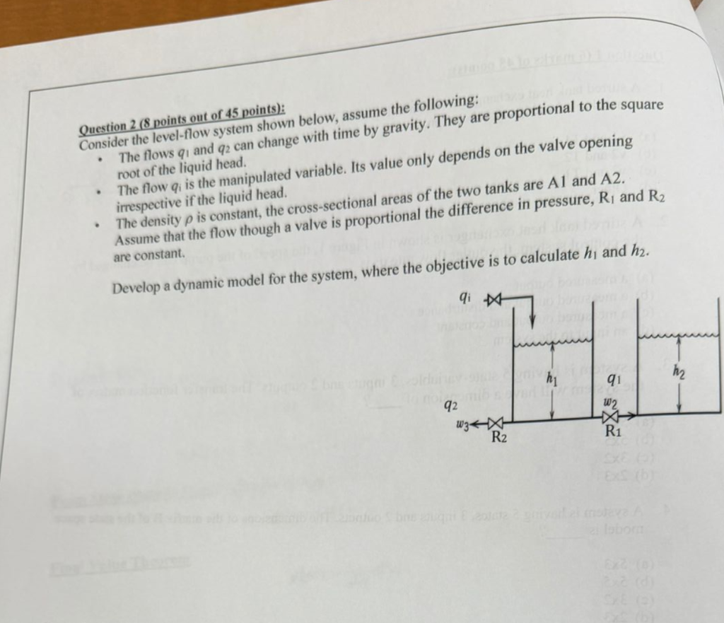 v
cussion 8 pups ant SLB lowing:
i Jevel-flow system shown below, assume the fo A \
rere q pe ao can change With time by gravity: They are proportional glllicaquare |
root of the liquid head. i
+ The flow gi is the manipulated variable. Its value only depends on the valve opening
imespective if the liquid head.
+ The density p is constant, the cross-sectional areas of the tWO tanks are Al and A2.
Assume that the flow though a valve is proportional the difference In pressure, Ri and Rz
are constant.
Develop a dynamic model for the system, where the objective is to calculate hy and hz.
aq a
| hy
L: fey ;
wy
>< <
Rz Ri
v
cussion 8 pups ant SLB lowing:
i Jevel-flow system shown below, assume the fo A \
rere q pe ao can change With time by gravity: They are proportional glllicaquare |
root of the liquid head. i
+ The flow gi is the manipulated variable. Its value only depends on the valve opening
imespective if the liquid head.
+ The density p is constant, the cross-sectional areas of the tWO tanks are Al and A2.
Assume that the flow though a valve is proportional the difference In pressure, Ri and Rz
are constant.
Develop a dynamic model for the system, where the objective is to calculate hy and hz.
aq a
| hy
L: fey ;
wy
>< <
Rz Ri
This is AI generated Response.
Asked by: Francis
Created at: 2026-03-06 00:05:08
Asked by: Francis
Created at: 2026-03-06 00:05:08
Final Answer:
Rendered
Raw Text
Did you like this answer?
Let's break down the problem **step-by-step**:
---
## **Step 1: Define Variables**
- \( h_1, h2 \): Liquid heights in tanks 1 and 2.
- \( A_1, A_2 \): Cross-sectional areas of tanks 1 and 2.
- \( q_i \): Inlet flow rate (manipulated, independent of head).
- \( q_1 \): Flow from tank 1 to tank 2 (through valve \( R_1 \)).
- \( q_2 \): Outflow from tank 1 (through valve \( R_2 \)).
- \( w_2 \): Inflow to tank 2 from tank 1 (same as \( q_1 \)).
- \( w_3 \): Outflow from tank 1 (same as \( q_2 \)).
- \( R_1, R_2 \): Flow resistances for valves.
- \( \rho \): Density of fluid (constant).
---
## **Step 2: Flow Relationships**
Given:
- \( q_1 \) and \( q_2 \) are proportional to the square root of the liquid head (difference).
For valves, the flow is also proportional to head difference:
- \( q_1 = \frac{h_1 - h_2}{R_1} \)
- \( q_2 = \frac{h_1}{R_2} \)
---
## **Step 3: Mass Balance for Each Tank**
### **Tank 1**
Rate of change of liquid volume in tank 1:
\[
\frac{d}{dt}(A_1 h_1) = \text{Inflow} - \text{Outflow}
\]
\[
A_1 \frac{dh_1}{dt} = q_i - q_1 - q_2
\]
### **Tank 2**
\[
A_2 \frac{dh_2}{dt} = q_1
\]
---
## **Step 4: Substitute Flow Relationships**
#### **For Tank 1:**
\[
A_1 \frac{dh_1}{dt} = q_i - \frac{h_1 - h_2}{R_1} - \frac{h_1}{R_2}
\]
#### **For Tank 2:**
\[
A_2 \frac{dh_2}{dt} = \frac{h_1 - h_2}{R_1}
\]
---
## **Step 5: Final Dynamic Model**
### **State-Space Equations**
\[
\boxed{
\begin{align*}
A_1 \frac{dh_1}{dt} &= q_i - \frac{h_1 - h_2}{R_1} - \frac{h_1}{R_2} \\
A_2 \frac{dh_2}{dt} &= \frac{h_1 - h_2}{R_1}
\end{align*}
}
\]
---
### **Explanation**
- The first equation is the dynamic balance for tank 1: input minus the two outputs.
- The second equation is the dynamic balance for tank 2: the only input is from tank 1.
---
## **Summary Table**
| State Variable | Differential Equation |
|:--------------:|:---------------------|
| \( h_1 \) | \( A_1 \frac{dh_1}{dt} = q_i - \frac{h_1 - h_2}{R_1} - \frac{h_1}{R_2} \) |
| \( h_2 \) | \( A_2 \frac{dh_2}{dt} = \frac{h_1 - h_2}{R_1} \) |
---
### **These two coupled ODEs form the dynamic model for the given system.**
📢 Instructions:
- Ask anything relatd to above question only.
- For new Question goto :