Give step-by-step solution with explanation and final answer:3) Consider the two-port network shown below. ¢. 200, [] Parl \ " Zz : Pork 2 2 7 6 Calculate the S-parameters Sy; and Sy; in terms of the impedances Z, Z,,, Z3, inside the network if the characteristic impedance is Z,. DO NOT calculate the other two missing S-parameters. Hint: S; may also be in terms of Sy;.
Question:
Give step-by-step solution with explanation and final answer: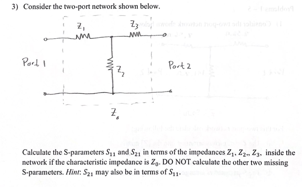 3) Consider the two-port network shown below.
¢. 200,
[]
Parl \ " Zz : Pork 2
2
7
6
Calculate the S-parameters Sy; and Sy; in terms of the impedances Z, Z,,, Z3, inside the
network if the characteristic impedance is Z,. DO NOT calculate the other two missing
S-parameters. Hint: S; may also be in terms of Sy;.
3) Consider the two-port network shown below.
¢. 200,
[]
Parl \ " Zz : Pork 2
2
7
6
Calculate the S-parameters Sy; and Sy; in terms of the impedances Z, Z,,, Z3, inside the
network if the characteristic impedance is Z,. DO NOT calculate the other two missing
S-parameters. Hint: S; may also be in terms of Sy;.
This is AI generated Response.
Asked by: M Murali
Created at: 2025-10-26 18:33:18
Asked by: M Murali
Created at: 2025-10-26 18:33:18
Final Answer:
Rendered
Raw Text
Did you like this answer?
Let's analyze the problem step-by-step.
---
## **Given Data:**
- The network consists of three impedances: \( Z_1, Z_2, Z_3 \).
- The impedance between the two ports (Port 1 and Port 2) is \( Z_ \).
- The impedances are arranged as shown:
- \( Z_1 \) between Port 1 and the node.
- \( Z_3 \) between the node and Port 2.
- \( Z_2 \) between the node and ground (or between the node and the common reference).
---
## **Objective:**
Calculate the S-parameters \( S_{11} \) and \( S_{21} \) in terms of the impedances \( Z_1, Z_2, Z_3 \).
---
## **Step 1: Understanding the configuration**
The network is a two-port network with the following configuration:
- Input port at Port 1.
- Output port at Port 2.
- The node in the middle connects impedances \( Z_1, Z_2, Z_3 \).
The key is to relate the incident and reflected waves at the ports to the impedance network.
---
## **Step 2: Express the S-parameters**
Recall the definitions:
\[
S_{11} = \frac{\text{Reflected wave at port 1}}{\text{Incident wave at port 1}} \quad \text{(when port 2 is matched)}
\]
\[
S_{21} = \frac{\text{Transmitted wave at port 2}}{\text{Incident wave at port 1}} \quad \text{(when port 2 is matched)}
\]
---
## **Step 3: Write the impedance relations**
Assuming the characteristic impedance of the ports is \( Z_ \), and the network is linear, we can express the input and output waves as:
\[
a_1, b_1 \text{ at port 1}
\]
\[
a_2, b_2 \text{ at port 2}
\]
where:
\[
a_1 = \text{incident wave at port 1}
\]
\[
b_1 = \text{reflected wave at port 1}
\]
and similarly for port 2.
---
## **Step 4: Find the relation between waves and impedance network**
The key is to find the input impedance seen at port 1, \( Z_{in} \), and the transfer impedance for transmission.
### **Input impedance seen at Port 1:**
The network between port 1 and port 2 can be viewed as a two-port network with certain impedance relations.
---
## **Step 5: Use the impedance matrix approach**
The impedance parameters relate voltages and currents:
\[
\begin{bmatrix}
V_1 \\
V_2
\end{bmatrix}
=
\begin{bmatrix}
Z_{11} & Z_{12} \\
Z_{21} & Z_{22}
\end{bmatrix}
\begin{bmatrix}
I_1 \\
I_2
\end{bmatrix}
\]
But since the problem asks for S-parameters in terms of the impedances \( Z_1, Z_2, Z_3 \), and the network resembles a T-network or Pi-network, the S-parameters can be directly related to the impedance network.
---
## **Step 6: Express \(S_{11}\) and \(S_{21}\) in terms of impedances**
### **Reflection coefficient \( S_{11} \):**
\[
S_{11} = \frac{Z_{in} - Z_}{Z_{in} + Z_}
\]
where \( Z_{in} \) is the input impedance seen at port 1 when port 2 is matched.
---
### **Transmission coefficient \( S_{21} \):**
\[
S_{21} = \frac{2 Z_}{Z_{in} + Z_}
\]
---
## **Step 7: Find \( Z_{in} \) in terms of \( Z_1, Z_2, Z_3 \)**
The impedance looking into port 1, with port 2 terminated in \( Z_ \), can be derived as:
\[
Z_{in} = Z_1 + \left( Z_2 \parallel Z_3 \right)
\]
where:
\[
Z_2 \parallel Z_3 = \frac{Z_2 Z_3}{Z_2 + Z_3}
\]
---
## **Final expressions:**
\[
\boxed{
\begin{aligned}
Z_{in} &= Z_1 + \frac{Z_2 Z_3}{Z_2 + Z_3}
\end{aligned}
}
\]
---
## **Step 8: Write the S-parameters**
\[
\boxed{
S_{11} = \frac{Z_{in} - Z_}{Z_{in} + Z_}
}
\]
\[
\boxed{
S_{21} = \frac{2 Z_}{Z_{in} + Z_}
}
\]
with
\[
Z_{in} = Z_1 + \frac{Z_2 Z_3}{Z_2 + Z_3}
\]
---
## **## **Final answers:**
\[
\boxed{
\textbf{S}_{11} = \frac{Z_1 + \frac{Z_2 Z_3}{Z_2 + Z_3} - Z_}{Z_1 + \frac{Z_2 Z_3}{Z_2 + Z_3} + Z_}
}
\]
\[
\boxed{
\textbf{S}_{21} = \frac{2 Z_}{Z_1 + \frac{Z_2 Z_3}{Z_2 + Z_3} + Z_}
}
\]
---
**Note:** The derivation assumes the network is linear, reciprocal, and the port characteristic impedance is \( Z_ \).
📢 Instructions:
- Ask anything relatd to above question only.
- For new Question goto :