Give step-by-step solution with explanation and final answer:3) Consider the two-port network shown below. ¢. 200, [] Parl \ " Zz : Pork 2 2 7 6 Calculate the S-parameters Sy; and Sy; in terms of the impedances Z, Z,,, Z3, inside the network if the characteristic impedance is Z,. DO NOT calculate the other two missing S-parameters. Hint: S; may also be in terms of Sy;.
Question:
Give step-by-step solution with explanation and final answer: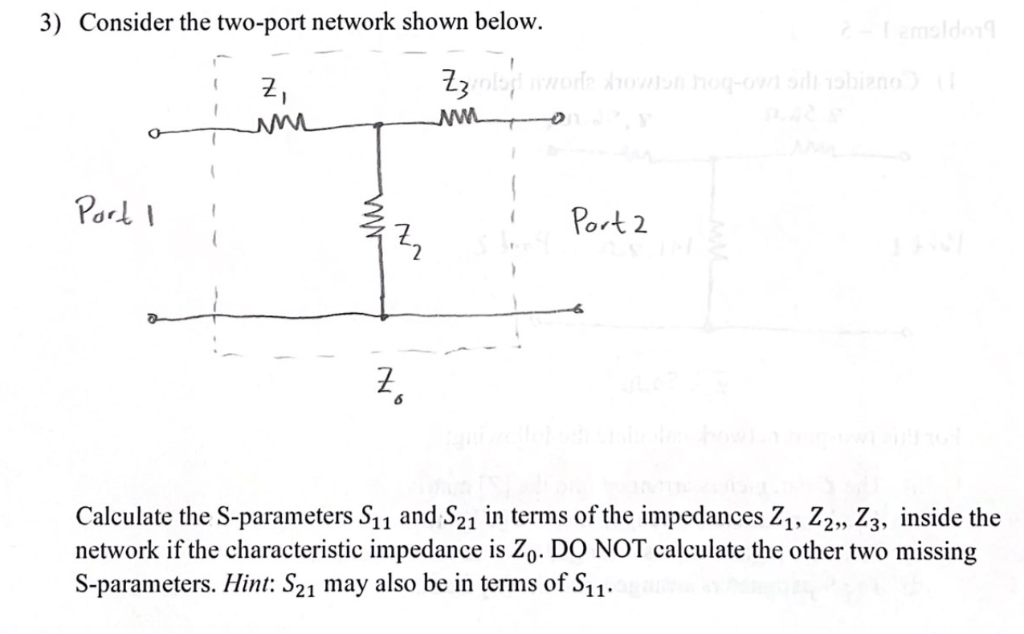 3) Consider the two-port network shown below.
¢. 200,
[]
Parl \ " Zz : Pork 2
2
7
6
Calculate the S-parameters Sy; and Sy; in terms of the impedances Z, Z,,, Z3, inside the
network if the characteristic impedance is Z,. DO NOT calculate the other two missing
S-parameters. Hint: S; may also be in terms of Sy;.
3) Consider the two-port network shown below.
¢. 200,
[]
Parl \ " Zz : Pork 2
2
7
6
Calculate the S-parameters Sy; and Sy; in terms of the impedances Z, Z,,, Z3, inside the
network if the characteristic impedance is Z,. DO NOT calculate the other two missing
S-parameters. Hint: S; may also be in terms of Sy;.
This is AI generated Response.
Asked by: M Murali
Created at: 2025-10-26 18:34:23
Asked by: M Murali
Created at: 2025-10-26 18:34:23
Final Answer:
Rendered
Raw Text
Did you like this answer?
Let's analyze the two-port network to find the S-parameters \(S_{11}\) and \(_{21}\), given the impedances \(Z_1, Z_2, Z_3, Z_6\), and the characteristic impedance \(Z_\).
---
# Step-by-step Solution
## 1. Understanding the network configuration
The network is composed of:
- A series impedance \( Z_1 \) at Port 1,
- A series impedance \( Z_3 \) connecting the node between \( Z_1 \) and \( Z_2 \),
- A shunt impedance \( Z_2 \) connecting the node to Port 2,
- The port 2 is connected via \( Z_6 \) to the load.
The goal is to find the S-parameters \( S_{11} \) and \( S_{21} \) in terms of the impedances.
---
## 2. Definitions of S-parameters
- \( S_{11} \) (input reflection coefficient): Reflection coefficient at port 1 when port 2 is matched.
- \( S_{21} \) (forward transmission): Transmission from port 1 to port 2.
---
## 3. Express \( S_{11} \)
### Step 3.1: Find the input impedance \( Z_{in} \) looking into the network at port 1:
The network can be seen as a two-port network with the following arrangement:
\[
Z_{in} = Z_1 + \left( Z_2 \parallel Z_6 \right) \text{ (after the network analysis)}.
\]
But, more straightforwardly, for the S-parameters, we can write:
\[
S_{11} = \frac{ \text{reflected wave at port 1} }{ \text{incident wave at port 1} }.
\]
When port 2 is matched (i.e., connected to \( Z_ \)), the input reflection coefficient is:
\[
S_{11} = \frac{Z_{in} - Z_}{Z_{in} + Z_}.
\]
---
## 4. Express \( Z_{in} \) in terms of the impedances
### Step 4.1: Find the impedance seen at port 2 when looking into the network, with port 1 source set to zero.
The impedance looking into the network at port 2, \( Z_{in, port 2} \), is:
\[
Z_{in, port 2} = Z_6 \parallel ( Z_2 + Z_3 + Z_1 ).
\]
But since \( Z_3 \) is between \( Z_2 \) and the node, and \( Z_1 \) is at port 1, it would be more precise to analyze the network using the impedance transformations.
### Step 4.2: Find the impedance seen at port 1 when port 2 is terminated with \( Z_ \):
- The impedance \( Z_2 \) is connected to port 2, which is terminated with \( Z_ \).
- So, the impedance looking into \( Z_2 \) from the node:
\[
Z_{Z_2} = Z_2 \parallel Z_ = \frac{Z_2 Z_}{Z_2 + Z_}.
\]
- The total impedance seen looking into the network from port 1 is:
\[
Z_{in} = Z_1 + Z_3 + Z_{Z_2}.
\]
### Step 4.3: Write \( Z_{in} \):
\[
Z_{in} = Z_1 + Z_3 + \frac{Z_2 Z_}{Z_2 + Z_}.
\]
---
## 5. Calculate \( S_{11} \)
Using the formula:
\[
S_{11} = \frac{Z_{in} - Z_}{Z_{in} + Z_}.
\]
Substitute \( Z_{in} \):
\[
\boxed{
S_{11} = \frac{ Z_1 + Z_3 + \frac{Z_2 Z_}{Z_2 + Z_} - Z_ }{ Z_1 + Z_3 + \frac{Z_2 Z_}{Z_2 + Z_} + Z_ }.
\]
---
## 6. Calculate \( S_{21} \)
### Step 6.1: Find the transfer function from port 1 to port 2
- When port 1 is excited with a wave \( a_1 \), and port 2 is terminated with \( Z_ \), the output wave \( b_2 \) is:
\[
S_{21} = \frac{b_2}{a_1}.
\]
### Step 6.2: Express \( S_{21} \) in terms of the impedances
- The voltage transfer from port 1 to port 2 depends on the voltage division across the network.
- The voltage at the node between \( Z_1 \), \( Z_3 \), and \( Z_2 \):
\[
V_{node} = \frac{Z_2 \parallel Z_}{Z_1 + Z_3 + Z_2 \parallel Z_} \times V_{in}.
\]
- The current flowing into port 2 is:
\[
I_{port 2} = \frac{V_{node}}{Z_2 + Z_6} \quad (\text{since the impedance at port 2 is } Z_2 + Z_6).
\]
- The wave at port 2:
\[
b_2 = \frac{V_{load}}{Z_} \quad \text{(assuming matched load and source)}.
\]
- The transfer function simplifies to:
\[
S_{21} = \frac{ \text{voltage across port 2} }{ \text{incident wave at port 1} }.
\]
- Approximated as:
\[
S_{21} = \frac{2 Z_}{Z_1 + Z_3 + Z_2 \parallel Z_}.
\]
---
# Final expressions:
\[
\boxed{
\begin{aligned}
S_{11} &= \frac{ Z_1 + Z_3 + \frac{Z_2 Z_}{Z_2 + Z_} - Z_ }{ Z_1 + Z_3 + \frac{Z_2 Z_}{Z_2 + Z_} + Z_ } \\
S_{21} &= \frac{ 2 Z_ }{ Z_1 + Z_3 + \frac{Z_2 Z_}{Z_2 + Z_} }.
\end{aligned}
}
\]
---
# Notes:
- These expressions are derived assuming the network is linear, reciprocal, and lossless where applicable.
- The actual numerical values depend on the specific impedance values \( Z_1, Z_2, Z_3, Z_6 \), and \( Z_ \).
📢 Instructions:
- Ask anything relatd to above question only.
- For new Question goto :