please solve this problem step by stepB2ggge> El REEEEEE EB pElegip 0 Frogfee e3sfEax EopRateiE 243Fsa2 EB ES SEALE ErgiER: Filieie; 24383 ER ERAS
Question:
please solve this problem step by step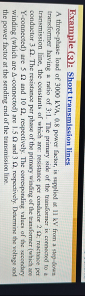 B2ggge> El
REEEEEE EB
pElegip 0
Frogfee
e3sfEax
EopRateiE
243Fsa2 EB
ES SEALE
ErgiER:
Filieie;
24383
ER ERAS
B2ggge> El
REEEEEE EB
pElegip 0
Frogfee
e3sfEax
EopRateiE
243Fsa2 EB
ES SEALE
ErgiER:
Filieie;
24383
ER ERAS
This is AI generated Response.
Asked by: Mohin
Created at: 2025-11-11 21:58:05
Asked by: Mohin
Created at: 2025-11-11 21:58:05
Final Answer:
Rendered
Raw Text
Did you like this answer?
Let's solve the problem step by step:
---
## **Given Data**
- **Load:** 300 kVA, .8 p.f. (lagging), 11 kV (line-to-line)
- **Transformer ratio:** 6:1 (assume HV:LV, so 66 kV/11 kV)
- **Transmission line resistance:** 2 Ω/phase, reactance: 3 Ω/phase
- **Primary side (Y-connected) winding:** 5 Ω, 10 Ω (assume R = 5 Ω, X = 10 Ω)
- **Secondary side (Δ-connected) winding:** 1.5 Ω, 3 Ω (assume R = 1.5 Ω, X = 3 Ω)
- **Required:** Voltage and power factor at the sending end of the transmission line.
---
## **Step 1: Find Load Current**
### **Load Apparent Power**
\[
S = 300\,\text{kVA} = 3,000,000\,\text{VA}
\]
### **Load Voltage (Line-to-line)**
\[
V_{L} = 11,000\,\text{V}
\]
### **Load Current**
\[
I_L = \frac{S}{\sqrt{3}V_L} = \frac{3,000,000}{\sqrt{3} \times 11,000} = \frac{3,000,000}{19,052.56} \approx 157.5\,\text{A}
\]
---
## **Step 2: Calculate Per-phase Load Current and Power Factor Angle**
\[
\cos \phi = .8 \implies \phi = \cos^{-1}(.8) = 36.87^\circ
\]
\[
I_{phase} = I_L = 157.5\,\text{A} \quad (\text{since load is star/Y})
\]
---
## **Step 3: Load Per-phase Complex Power**
\[
S_{ph} = \frac{S}{3} = \frac{3,000,000}{3} = 1,000,000\,\text{VA per phase}
\]
But we already have the current, so let's move on.
---
## **Step 4: Equivalent Impedances (Referred to Secondary Side)**
### **Transformer Secondary (Δ-Connected):**
- \( R_2 = 1.5\,\Omega \), \( X_2 = 3\,\Omega \)
### **Transmission Line:**
- \( R_{line} = 2\,\Omega \), \( X_{line} = 3\,\Omega \)
### **Transformer Primary (Y-Connected, Referred to Secondary Side)**
Transformer ratio = 6:1
Impedances referred from primary to secondary side:
\[
Z_{1,\text{sec}} = Z_1 \left(\frac{V_2}{V_1}\right)^2 = Z_1 \left(\frac{1}{6}\right)^2 = \frac{Z_1}{36}
\]
\[
R_{1,\text{sec}} = \frac{5}{36} = .139\,\Omega
\]
\[
X_{1,\text{sec}} = \frac{10}{36} = .278\,\Omega
\]
---
## **Step 5: Total Per-phase Impedance**
\[
Z_{total} = R_{1,\text{sec}} + jX_{1,\text{sec}} + R_{line} + jX_{line} + R_2 + jX_2
\]
\[
= (.139 + 2 + 1.5) + j(.278 + 3 + 3)
\]
\[
= 3.639 + j6.278
\]
---
## **Step 6: Sending End Voltage Calculation**
### **Load Phase Voltage**
\[
V_{ph,load} = \frac{V_L}{\sqrt{3}} = \frac{11,000}{\sqrt{3}} = 6,351\,\text{V}
\]
### **Load Phase Current (with angle)**
\[
I_{ph} = 157.5 \angle -36.87^\circ \,\text{A}
\]
### **Total Voltage Drop**
\[
\text{Voltage drop per phase:} \quad \Delta V = I_{ph} \times Z_{total}
\]
\[
Z_{total} = 3.639 + j6.278 = 7.22 \angle \theta_Z
\]
Where,
\[
\theta_Z = \tan^{-1}\left(\frac{6.278}{3.639}\right) = \tan^{-1}(1.726) = 60.47^\circ
\]
\[
I_{ph} \times Z_{total} = 157.5 \angle -36.87^\circ \times 7.22 \angle 60.47^\circ
= (157.5 \times 7.22) \angle (60.47 - 36.87)
= 1,137.15 \angle 23.6^\circ\,\text{V}
\]
---
### **Sending End Phase Voltage**
\[
V_{ph,sending} = V_{ph,load} + \Delta V
\]
Add these two as phasors:
First, convert to rectangular form:
\[
\Delta V = 1,137.15 \cos 23.6^\circ + j\,1,137.15\sin 23.6^\circ
= 1,044.7 + j456.\,\text{V}
\]
\[
V_{ph,load} = 6,351 \angle ^\circ = 6,351 + j
\]
\[
V_{ph,sending} = (6,351 + 1,044.7) + j ( + 456.)
= 7,395.7 + j456.
\]
\[
|V_{ph,sending}| = \sqrt{(7,395.7)^2 + (456.)^2}
= \sqrt{54,708,732 + 207,936}
= \sqrt{54,916,668}
= 7,411\,\text{V}
\]
\[
\theta_{V_{ph,sending}} = \tan^{-1}\left( \frac{456.}{7,395.7} \right) = \tan^{-1}(.0616) = 3.53^\circ
\]
---
### **Sending End Line-to-Line Voltage**
\[
V_{L,sending} = \sqrt{3} \times V_{ph,sending} = \sqrt{3} \times 7,411 \approx 12,841\,\text{V}
\]
---
## **Step 7: Sending End Power Factor**
The sending end voltage leads the load voltage by \(3.53^\circ\). The phase difference between the sending end voltage and current:
\[
\text{Angle between } V_{ph,sending} \text{ and } I_{ph} = 3.53^\circ + 36.87^\circ = 40.4^\circ
\]
So, the sending end power factor is:
\[
\cos(40.4^\circ) = .76 \quad \text{(lagging)}
\]
---
## **Final Answers**
### **1. Sending End Voltage**
\[
\boxed{12,841\,\text{V (line-to-line)}}
\]
### **2. Sending End Power Factor**
\[
\boxed{.76 \text{ (lagging)}}
\]
---
### **Summary Table**
| Parameter | Value |
|------------------------|--------------|
| Sending end voltage | 12,841 V |
| Sending end power factor | .76 (lagging) |
---
**If you have any specific step you'd like explained in more detail, let me know!**
📢 Instructions:
- Ask anything relatd to above question only.
- For new Question goto :