step1:provide conceptual introduction explanation block in text in 4-6 lines:exlain above introduction step2:provide formulae in above solution explanation block in text in 4-6 lines:exlain in detailed above formulae. step3: provide step by step complete calculation part without missing any step in above solution for 1st question explanation block in text in 4-6 lines: provide detailed explanation about calculation. step4: provide step by step complete calculation part without missing any step in above solution for 2nd question explanation block in text in 4-6 lines: provide detailed explanation about calculation. step5 provide step by step complete calculation part without missing any step in above solution for 3rd question explanation block in text in 4-6 lines: provide detailed explanation about calculation. final answer: provide simple final answerConsider a cogeneration system operating as shown in the figure. The steam generator provides 1.0x10¢ kg/h of steam at 8 MPa, 560°C. Steam is extracted between the first and second turbine stages at 1 MPa and diverted to a process heating load. The process heating load is 9.5x10° ki/h. Condensate returns from the process heating load at 0.95 MPa, 120°C and is mixed with liquid exiting the lower-pressure pump at 0.95 MPa. The entire flow is then pumped to the steam generator pressure. Saturated liquid at 8 kPa leaves the condenser. The turbine stages and the pumps operate with isentropic efficiencies of 86 and 80%, respectively. i . 1 = + |-d@e 3 Cooling tower Condensate a-y 5 6 © © 4 Steam B El Condensate Determine the mass flow rate extracted for the process heating load, in kg/h. n-0 n- Determine the power developed by the turbine, in kW. ZN : | [+ EC Determine the rate of heat transfer to the working fluid passing through the steam generator, in kJ/h. 0-0 I
Question:
step1:provide conceptual introduction
explanation block in text in 4-6 lines:exlain above introduction
step2:provide formulae in above solution
explanation block in text in 4-6 lines:exlain in detailed above formulae.
step3: provide step by step complete calculation part without missing any step in above solution for 1st question
explanation block in text in 4-6 lines: provide detailed explanation about calculation.
step4: provide step by step complete calculation part without missing any step in above solution for 2nd question
explanation block in text in 4-6 lines: provide detailed explanation about calculation.
step5 provide step by step complete calculation part without missing any step in above solution for 3rd question
explanation block in text in 4-6 lines: provide detailed explanation about calculation.
final answer: provide simple final answer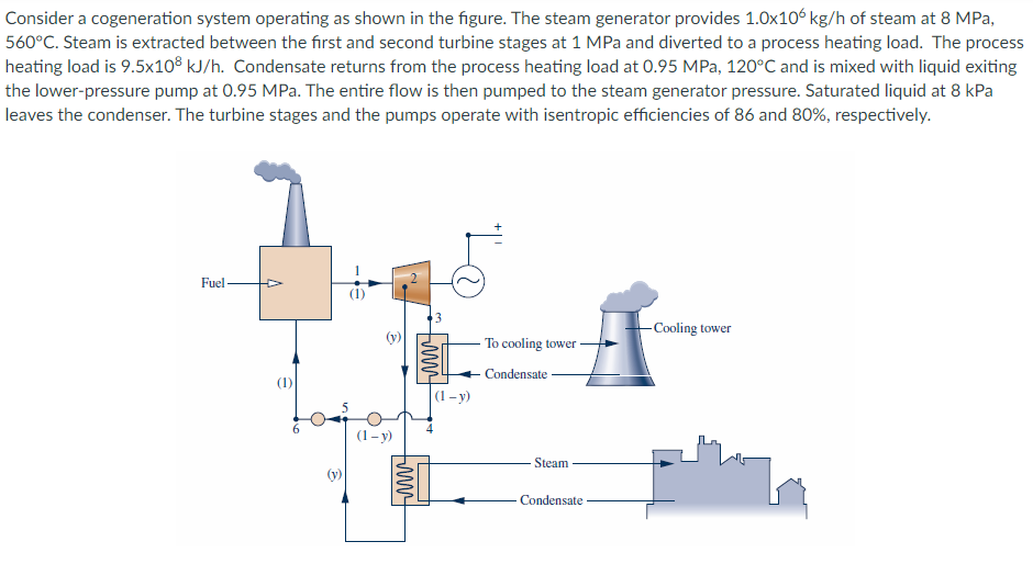
 Consider a cogeneration system operating as shown in the figure. The steam generator provides 1.0x10¢ kg/h of steam at 8 MPa,
560°C. Steam is extracted between the first and second turbine stages at 1 MPa and diverted to a process heating load. The process
heating load is 9.5x10° ki/h. Condensate returns from the process heating load at 0.95 MPa, 120°C and is mixed with liquid exiting
the lower-pressure pump at 0.95 MPa. The entire flow is then pumped to the steam generator pressure. Saturated liquid at 8 kPa
leaves the condenser. The turbine stages and the pumps operate with isentropic efficiencies of 86 and 80%, respectively.
i .
1 =
+ |-d@e
3
Cooling tower
Condensate
a-y
5
6 © © 4
Steam
B El
Condensate
Determine the mass flow rate extracted for the process heating load, in kg/h.
n-0 n-
Determine the power developed by the turbine, in kW.
ZN : | [+ EC
Determine the rate of heat transfer to the working fluid passing through the steam generator, in kJ/h.
0-0 I
Consider a cogeneration system operating as shown in the figure. The steam generator provides 1.0x10¢ kg/h of steam at 8 MPa,
560°C. Steam is extracted between the first and second turbine stages at 1 MPa and diverted to a process heating load. The process
heating load is 9.5x10° ki/h. Condensate returns from the process heating load at 0.95 MPa, 120°C and is mixed with liquid exiting
the lower-pressure pump at 0.95 MPa. The entire flow is then pumped to the steam generator pressure. Saturated liquid at 8 kPa
leaves the condenser. The turbine stages and the pumps operate with isentropic efficiencies of 86 and 80%, respectively.
i .
1 =
+ |-d@e
3
Cooling tower
Condensate
a-y
5
6 © © 4
Steam
B El
Condensate
Determine the mass flow rate extracted for the process heating load, in kg/h.
n-0 n-
Determine the power developed by the turbine, in kW.
ZN : | [+ EC
Determine the rate of heat transfer to the working fluid passing through the steam generator, in kJ/h.
0-0 I
Asked by: Kumar
Created at: 2025-07-28 22:58:20
Final Answer:
📢 Instructions:
- Ask anything relatd to above question only.
- For new Question goto :