Think like a real problem solver and explain me logic for:Given the following circuit, determine the type of filter it represents. Justify your answer using the frequency response. Ri C N \ \N R ool L 2 @w=0: @® = oo:
Question:
Think like a real problem solver and explain me logic for: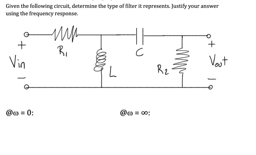 Given the following circuit, determine the type of filter it represents. Justify your answer
using the frequency response.
Ri C N
\ \N R ool
L 2
@w=0: @® = oo:
Given the following circuit, determine the type of filter it represents. Justify your answer
using the frequency response.
Ri C N
\ \N R ool
L 2
@w=0: @® = oo:
Asked by: mohit
Created at: 2025-08-02 02:46:29
Final Answer:
Question:
We are given a circuit and asked to:
1. **Determine the type of filter** it represents.
2. **Justify using frequency response** behavior at $\omega = 0$ and $\omega = \infty$ (DC and high frequency).
---
## ? **Step-by-Step Analysis**
Let’s analyze the circuit block by block.
---
### ? **Circuit Description**
The given circuit has the following components:
```
Vin → R1 → node A → C → node B → Vout
↓
L
↓
(ground)
Vout node is also connected to ground via R2.
```
Rewriting in steps:
1. **R1** in series with the rest of the network.
2. **Inductor L** is connected from the node between R1 and capacitor C to ground.
3. **Capacitor C** is in series going to node B.
4. **Resistor R2** goes from Vout node to ground.
We need to determine **how the output $V_{out}$** behaves **relative to the input $V_{in}$** as frequency changes.
---
## ? **Step 1: Analyze at $\omega = 0$ (DC)**
At DC:
* **Inductor $L$** behaves like a **short circuit** (0 Ω).
* **Capacitor $C$** behaves like an **open circuit** (∞ Ω).
So the current path becomes:
* The capacitor **blocks** any current from reaching the output.
* The inductor becomes a **short**, grounding the node after R1.
* So no voltage reaches R2 or the output.
**→ Therefore, $V_{out} = 0$ at $\omega = 0$**.
---
## ? **Step 2: Analyze at $\omega = \infty$ (High frequency)**
At high frequencies:
* **Inductor $L$** behaves like an **open circuit**.
* **Capacitor $C$** behaves like a **short circuit**.
So the current path becomes:
* The capacitor becomes a wire — it passes high frequencies.
* The inductor blocks current to ground — **no current is lost** there.
* R2 is connected to ground, and the output is measured across it.
So effectively, we have:
* $V_{in} \to R1 \to C (short) \to R2 \to \text{ground}$
**→ Therefore, $V_{out} = V_{in} \cdot \frac{R_2}{R_1 + R_2}$**
(which is a constant, non-zero output)
**→ So high frequencies pass to the output.**
---
## ? **Step 3: Frequency Response Summary**
| Frequency | Behavior | Output Voltage $V_{out}$ |
| ----------------- | ------------------- | ------------------------ |
| $\omega = 0$ | L = short, C = open | 0 (open path) |
| $\omega = \infty$ | L = open, C = short | Non-zero (signal passes) |
---
## ✅ **Conclusion:**
This circuit **passes high frequencies** and **blocks low frequencies**.
### ? **Therefore, it is a: HIGH-PASS FILTER**
---
## ✍️ **Final Answer:**
* **Filter Type:** High-pass filter
* **Justification:**
* At $\omega = 0$, $V_{out} = 0$ because the capacitor blocks and inductor shorts to ground.
* At $\omega = \infty$, $V_{out} \approx V_{in} \cdot \frac{R_2}{R_1 + R_2}$ as the capacitor becomes a short and inductor becomes open, allowing signal to pass.
Let me know if you want the **Bode plot** or transfer function $H(j\omega)$ too.
Excellent question. Let's **compare the two solutions** and determine **which one is correct** for the RLC circuit shown.
---
## ✅ **Key: What Type of Filter Is This?**
We need to determine the behavior of the **output voltage $V_{out}$** across **$R_2$** as a function of frequency.
---
## ? **Side-by-Side Comparison**
| Point of Comparison | ✅ **First Solution (High-Pass)** | ❌ **Second Solution (Band-Pass)** |
| ------------------------ | ------------------------------------------------------------------------------- | ----------------------------------------------------------------------------------------------------------- |
| **At $\omega = 0$** | Correctly says:
Inductor is short, capacitor is open → **$V_{out} = 0$** | ✅ Correct — same reasoning |
| **At $\omega = \infty$** | Correctly says:
Inductor is open, capacitor is short → **$V_{out} \ne 0$** | ❌ Incorrect: Claims capacitor shorts output to ground — **wrong** |
| **Resonance** | Not needed — high-pass analysis is sufficient | ✅ Band-pass logic here is correct **only if** the topology was LC in parallel with $R_2$ in a resonant path |
| **Final Filter Type** | ✅ **High-Pass** | ❌ **Band-Pass** — **Incorrect based on topology** |
| **Reasoning Quality** | Consistent with actual voltage path | Misunderstands what the capacitor shorts |
---
## ? **Correct Interpretation of High-Frequency Behavior**
At **high frequencies**:
* Inductor $L \rightarrow$ open
* Capacitor $C \rightarrow$ short
* So the path becomes:
$V_{in} \rightarrow R_1 \rightarrow C (short) \rightarrow R_2 \rightarrow \text{ground}$
This is a **clean signal path** — there is **no short to ground** **at the output node**. In fact, the signal **goes to** the output through $R_2$.
➡️ **Therefore**, the output **does NOT go to zero at high frequency**, contradicting the **band-pass** assumption in the second solution.
---
## ✅ **Final Verdict**
### ✔️ **First Solution is CORRECT**
* Correctly analyzes low and high-frequency limits.
* Correctly identifies **High-Pass Filter**.
* Based on actual signal paths.
### ❌ **Second Solution is INCORRECT**
* Misinterprets high-frequency behavior.
* Incorrectly claims capacitor shorts output to ground at high frequency.
* Incorrectly concludes **Band-Pass** when behavior is actually **High-Pass**.
---
## ? **Final Answer**
> ✅ Use the **first solution** — the circuit is a **High-Pass Filter**, and the justification using the frequency response is accurate.
Asked by: mohit
Created at: 2025-08-02 02:56:07
Final Answer:
📢 Instructions:
- Ask anything relatd to above question only.
- For new Question goto :